Showing posts with label digital storage oscilloscope. Show all posts

Wednesday, February 20, 2013

DIGITAL STORAGE OSCILLOSCOPES: CHOOSING THE RIGHT BANDWIDTH


Because there are hundreds of models available with different specifications at a wide variety of prices, choosing the right oscilloscope can be intimidating and confusing for many engineers and technicians. In this article we’ll look at a few aspects of digital storage oscilloscopes that are of particular importance in order to help you avoid a costly mistake.
Some things to consider before we get into the specifics of bandwidth are: where you’ll be using the oscilloscope, how many signals you’ll need to measure at one time, the minimum and maximum signal amplitudes you’ll be measuring, the highest frequency signal you’ll potentially measure, whether your signals are repetitive or single-shot, and whether you need to view signals in the frequency domain (i.e. spectrum analysis) and the time domain simultaneously.
Bandwidth
Bandwidth is the maximum signal frequency that can pass through the front-end amplifiers and the oscilloscope's bandwidth must be higher than the maximum frequency you’d like to measure. However, sufficient bandwidth isn’t the only consideration when making sure that a digital storage oscilloscope can capture a high-frequency signal accurately.
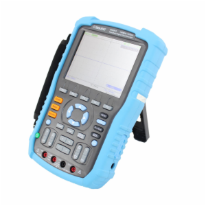
Oscilloscope manufacturers seek a certain type of frequency response when designing their instruments and this response is called the maximally flat envelope delay, or MFED. This type of frequency response provides superb pulse fidelity with very little undershoot, overshoot, and ringing. Because a digital storage oscilloscope is made up of amplifiers, attenuators, analog-to-digital converters, interconnects, and relays, maximally flat envelope delay response cannot be entirely realized — think of it more as an ideal.
Please note that the majority of oscilloscope manufacturers define bandwidth as the frequency at which a particular sine wave signal will be attenuated to seventy-one percent of its actual amplitude, i.e. the trace will be twenty-nine percent in error of the input signal.
Your signal will contain high-frequency harmonics if your input signal isn’t a pure sine wave; e.g. a twenty megahertz signal viewed on a twenty megahertz bandwidth oscilloscope will show up as a distorted and attenuated waveform. A good rule of thumb here is choosing an oscilloscope with a bandwidth five times higher than the maximum frequency signal you’d like to measure. The caveat here is that oscilloscopes with high bandwidths are more expensive, meaning you may have to compromise with regard to your oscilloscope’s bandwidth. Some oscilloscopes have bandwidths that aren’t available for all voltage ranges which is why should carefully read through the oscilloscope’s data sheet.

Wednesday, January 30, 2013

BENEFITS OF PC-BASED USB OSCILLOSCOPES


PC-based USB oscilloscopes, which display signal voltage as two-dimensional graphs and indicate amplitude distortions related to events and frequency, are used by hobbyists and professionals alike for testing hardware and research. Conventional oscilloscopes are typically stand-alone pieces of testing equipment that aren’t readily portable. PC-based oscilloscopes connect directly to your computer’s USB port and enable you to power the device, acquire and store data, and supply record evaluation; these features have given users more options and new techniques when using an oscilloscope.
PC-based oscilloscopes utilize your computer’s hardware — specifically its processor(s) — to display data on the computer’s screen and record that data on the computer’s hard drive or other storage devices. There are myriad modifications that can be done with PC-based oscilloscopes that aren’t practical for stand-alone oscilloscopes.
There are a wide variety of uses for PC-based oscilloscopes. Technicians use PC-based oscilloscopes as diagnostic tools for computer problems and maintenance work on all sorts of electrical equipment. PC-based oscilloscopes are also useful for everything from conducting electrocardiograms (medical professionals) to diagnosing issues with cars (automotive repair).
Modern computer processors are faster than they’ve ever been and their prices are dropping all the time — it’s no wonder that PC-based oscilloscopes are being used more often. In addition PC-based oscilloscopes can do everything that stand-alone units can but cost less and work with just about any computer. Old PCs are often significantly faster and more powerful than many stand-alone oscilloscopes that cost hundreds or even thousands of dollars, meaning that you can pull that ten-year-old computer out of storage, dust it off, and bring it back to life with an oscilloscope.
Furthermore data collected with a PC-based oscilloscope can be quickly and easily stored, shared, or exported as a result of a computer’s word processing and spreadsheet software, storage capacity, and networking capabilities. On top of that PC-based oscilloscopes offer better screen resolution and portability. It’s not hard to see why PC-based USB oscilloscopes have increased in popularity in recent years. Stand-alone oscilloscopes may soon be a thing of the past.

Thursday, January 24, 2013

USB OSCILLOSCOPE OVERVIEW


USB oscilloscopes, which allow you to take measurements of electrical impulses and observe constantly varying signal voltages, operate via one of your computer’s USB ports. An oscilloscope measures all detected signals and displays a graph indicating precisely how much impulses change for a specific time period. You will notice several things regarding a single signal: the signal’s frequency, voltage, duration, and the level of alternating and direct current. While standard oscilloscopes are powered by direct electrical connections, USB oscilloscopes derive their operating power from linking to your computer by way of its USB port.
In the past oscilloscopes were used sparingly because of their power requirements, but recent technical developments have led to portable oscilloscopes that can be powered by plugging into a USB port, making these multipurpose tools — which are used in a variety of applications from basic electronics to advanced physics testing and experimentation by hobbyists and professionals alike — standard equipment in many classrooms and laboratories.
The invention of USB-powered oscilloscopes has enabled them to be used in a number of new ways. Because USB oscilloscopes can be powered by a laptop computer, they can be used nearly anywhere. USB oscilloscopes also have the added convenience of quickly and efficiently downloading information to the computer to which it is attached. Another benefit of USB oscilloscopes is that the information they collect is instantly displayed on your computer. As a result of the speed at which information is transmitted to a computer, its easy for all the data taken by an oscilloscope to be shared between several viewers on different computers, which is an advantage for specialists who want to quickly distribute data to colleagues elsewhere.
There are a wide variety of USB oscilloscopes available including basic oscilloscopes for less demanding testing applications and more sophisticated (and expensive) oscilloscopes that feature better specifications, additional capability, and excellent accuracy. This diversity in the USB oscilloscope market makes these powerful pieces of test equipment suitable and cost-effective for a variety of disciplines, including everything from basic production jobs to more technical tasks like research and product development.

Friday, September 7, 2012

Types of Oscilloscope Waveforms


Most waveforms on digital storage oscilloscopes are easy to identify: there are sine, square, rectangular, triangle, sawtooth, step-, and pulse-shaped waves.
Good Ol’ Sine Waves
Sine waves are the fundamental waveform because of their prevalence and their harmonious mathematical properties. (It’s the same sine wave you had to learn in high school math class.) The voltage from your wall’s outlet makes a sine wave. Test signals from a signal generator’s oscillator circuit make sine waves. AC power sources make sine waves. You get the picture.
Then there’s the damped sine wave. You’re likely to see this in a circuit that oscillates while winding down over time. Whereas an ordinary sine wave rolls up and down with regularity, a damped sine wave rolls up and down while getting decreasing in amplitude — the wave gets closer to zero the longer it goes on.
Square and Rectangular Waves
Square waves are almost as common as sine waves. A square wave is, in essence, a voltage that turns on and off — or abruptly alternates between high and low — at recurring intervals. Television, radio, and computer circuitry frequently uses square waves for timing signals.
Rectangular waves are similar to square waves, save for the fact that the high and low intervals aren’t equal lengths.
Sawtooth and Triangle Waves
Linearly controlled voltages result in sawtooth and triangle waves on the digital storage oscilloscope. The voltage levels of these types of waves transition at a constant rate, and these transitions are called “ramps”.
Step- and Pulse-Shaped Waves
Signals like steps or pulses that occur just once are called single-shot or transient signals. A step represents a sudden change in voltage — it’s what you’d see if you flipped a power switch. If you flipped that power switch on and then off, then you’d get a pulse.
Computer components communicate with one another using pulses. Pulses are common in x-ray and communications equipment as well.