Showing posts with label digital multimeter. Show all posts

Wednesday, April 3, 2013

Multimeter Features Guide


There are a number of different features that differ from one multimeter to the next, some of which you’ll often use and others you may never use.
The most important feature is continuity, which allows you to test whether two things are electrically connected. Continuity testing with a peizo buzzer enables you to determine if your soldering is good, a wire is broken in the middle, and something isn’t connected in addition to allowing you to reverse-engineer or verify a design to a schematic.
Some other important features are resistance testing down to ten ohms or lower and up to one megaohm or higher, direct current voltage testing down to one hundred millivolts or lower and up to fifty volts, alternate current testing down to one volt and up to two hundred volts, and diode testing.
Because it’s easy to forget to turn off your multimeter’s power, auto-off is a great feature to have, which you rarely see on budget multimeters. Regardless of this feature you should get in the habit of turning off your multimeter after you finish using it.

If you know how to use it autoranging is a helpful feature and, typically, autoranging multimeters are of higher quality and have more features than simpler multimeters. Keep in mind that with some systems the current or voltage will be too sporadic for the autorange feature to keep up. Some users dislike autoranging because it slower and less precise.
Other optional but useful multimeter features are alternate and direct current testing, a stand for keeping the multimeter upright, a hold function to keep the maximum value on the screen enabling you to use the probes without staring at the screen, and common battery types (such as a nine volt or AAs).
Back-lit LCD multimeters are nice, but chances are you won’t be measuring circuits in the dark. If you need a multimeter that is visible in low light then by all means look for a back-lit model.
You don’t really need fancy probes for you multimeter — just some sturdy, reasonably-priced ones. Your leads will break down over time, generally at the flex point; however, probes are relatively inexpensive, so when you do break a probe, which you eventually will with enough use, you’ll be able to replace it for around five dollars.
Some features you’ll seldom use include a frequency counter, capacitance testing, inductance testing, duty cycle, transistor beta meter, and temperature probe.

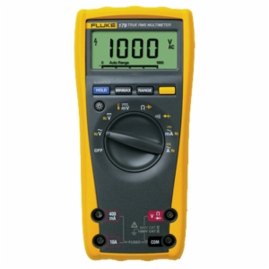
Wednesday, March 20, 2013

DIGITAL MULTIMETER TEST ENVIRONMENTS


While digital multimeters are still commonly used in benchtop testing, there are now a number of interconnect options for system integration; e.g., some multimeters offer hobbyists and engineers alike USB interfaces and general purpose interface buses for control via PC using test commands. Certain LabVIEW drivers allow one to integrate one’s multimeter into a larger test system. Then there are front-panel thermocouple inputs which allow one to connect directly to many prevalent temperature measurement sensors.
Indicating a multimeter’s susceptibility to noise, digital multimeters have specifications for normal mode rejection ratio and common mode rejection ratio with common values of over sixty decibels and one hundred twenty decibels. The noise produced by one’s multimeter is particularly important when measuring low signal levels, and electromagnetic interference standards influence compliance levels.
Because of its influence on throughput, a digital multimeter’s measurement speed — typically displayed as readings per second at a specific resolution level — is especially important in production environments.
A number of modern multimeters have resolution levels that one can program, thus simplifying balancing speed and accuracy. The integration period, which is the amount of time when a signal is sampled by the multimeter’s analog-to-digital convertor, is typically displayed in number of power line cycles; number of power line cycles made up of integer multiples — one, five, ten, etc. — will reduce the fifty/sixty hertz line pickup, which is the most common type of noise. One will have greater noise reduction with a larger number value with the caveat that measurementS will take longer to complete.
The number of analog-to-digital conversions averaged for each reading, or digital filtering, can stabilize readings with excess noise but, again, this will slow measurement times.
One’s multimeter measures internal voltages in order to retain stability and accuracy with temperature changes over time when a multimeter’s autozero is used, but overuse of autozero will negatively impact the multimeter’s reading rate. Throughput can be increased by disabling autozero, performing it at certain intervals, or programming the multimeter to use autozero during the load/unload cycle.
Speed specifications like range changing speed, autorange time, and function changing rate might also affect throughput, and hardware triggers are generally faster than software triggers. Certain digital multimeter’s have a microprocessor dedicated to triggers which can significantly reduce latency. Setting or response time is also important when one is testing high-impedance devices.
Speedy and accurate switching is notably important in production test environments, because hundreds or even thousands of devices have to be tested every shift, and newer models support hundreds of multiplexer channels or thousands of matrix crosspoints.

Friday, February 8, 2013

USING SHUNTS IN CONJUNCTION WITH DIGITAL PANEL METERS


In the medical world a shunt is a means of diverting, e.g., blood from its typical path to another route. Shunts work in a similar manner in the realm of electronics, allowing current to bypass one point in a circuit and travel to another point.
An example of this would be Christmas lights. Because they are set in series, when one bulb fails the entire circuit goes out. Modern lights prevent this with shunts: each bulb has its own shunt in order to pass the current along, so to speak, when a filament fails.
Circuits are commonly tested for current, resistance, and voltage. Some devices — e.g. ammeters, voltmeters, and ohmmeters — individually measure these parameters. Other devices, like digital multimeters, can test several parameters at once. Digital panel meters are used to measure, display, and record a circuit’s current, resistance, and voltage; but because they are continually subjected to the parameters which they measure, they are prone to damage. However, using panel meters in conjunction with shunts mitigates the risk of damage.
When you combine shunts and panel meters you end up with shunt-resistive circuits which enable you to circumvent predetermined levels of current surrounding a piece of electronic testing equipment. Using a shunt and panel meter together (i.e., a shunt resistor) reduces the excess flow of current through your instruments and helps keep them better protected.
Moreover, combining a shunt and digital panel meter can extend the range of the shunt, which is known as a meter shunt. When you divide current between parallel shunt resistors you increase the range of an ammeter by adding another parallel resistor. Let’s say your meter can only read between zero and one milliamperes but your test requires full-scale detection of one hundred milliamperes. In this situation you can use a shunt to take on the difference between the detection capabilities of your meter and the desired level of full-scale detection. With regard to our example, your shunt would have to be able to handle the remaining current (i.e., ninety-nine milliamperes).
Shunts have myriad uses in electronics testing, but their chief utility comes from their ability to protect delicate equipment and boost the capabilities of panel meters, making shunts exceedingly useful for those who do serious electronic testing.

Monday, November 26, 2012

TROUBLESHOOTING YOUR GUITAR’S VOLUME CONTROL


Your electric guitar’s volume and tone controls are a fast, convenient way to raise and lower your guitar’s bass, mid, treble, and output volume without having to make adjustments at the amplifier; this is extremely helpful when practicing and performing, enabling you to tweak your tone and volume in the middle of a song.
When your guitar’s volume control fails the wires and connections need to be inspected. You’ll want to use your digital multimeter (DMM) to measure the resistance in ohms of the volume potentiometer. Potentiometers, or pots, are the electronic components to which the guitar’s volume and tone knobs attach. The problem with your volume control can be easily isolated and repaired with this simple three-step troubleshooting guide.
(Note: You’ll need a digital multimeter and small Phillips-head screwdriver. Ensure that your guitar is not plugged in to anything while testing your volume controls and, if you have any active electronics, remove their batteries.)
Step One
Remove all plates, knobs, and pickguards preventing access to your guitar’s electronics. Gibson-style guitars usually have a plate on the back of the body that covers the guitar’s electronics. Fender-style guitars, on the other hand, are generally accessed from the front, requiring you to remove the pickguard and the knobs attached to the potentiometers.
Step Two
Check the volume control pot’s wires and connections for any loose soldering or shorts. A loose or broken connection might be the source of the problem and this can be easily fixed by resoldering the connection with your soldering iron.
Step Three
Next you’ll want to test the volume pot using your digital multimeter. Set the DMM’s meter dial to 200k on the ohm (Ω) section of the dial and then turn the guitar’s volume control all the way in one direction. Touch the digital multimeter’s probes to the middle terminal and one of the outside terminals (potentiometers have three terminals). After that turn the volume control in the opposite direction. Depending on the direction the knob is turned the reading on your DMM will increase or decrease. If the reading on your DMM doesn’t change or even show up you’ll know the volume pot is no longer functional and will need to be replaced. The good news is that volume pots are inexpensive and need simply to be soldered.

Thursday, October 4, 2012

A Figurative Battle Royale in Stompbox Prototyping


Let’s discuss perfboard versus PCB versus stripboard (a.k.a. Veroboard) when you’re ready to transfer a stompbox circuit design — which should done on breadboard since it is reusable and easy to modify — to something more permanent to be enclosed in an effects pedal. (If you’ve got the parts to spare it’s a good idea to leave your design on the breadboard for visual reference and in order to take measurements with a digital multimeter if the permanent design requires troubleshooting.)
PCB Versus Perfboard
Nowadays the majority of stompboxes and amplifiers are assembled on printed circuit boards (PCBs), which are a piece of fiberboard or plastic on which all components are connected by internal conductive traces — you simply solder the components into their holes and the connections are good to go. If you’ve ever bought a stompbox kit, chances are it came with a PCB and a bag of parts, which is a quick and easy way to build an effects pedal.
The real benefit of using perfboard in our context is that you’ll develop a greater understanding of how circuits come together and work and you’ll make turning a simple schematic into a working circuit in future designs much, much easier. Perfboard consists of tiny, copper-lined holes in rows and, when designing circuits using perfboard, you’ll manually manually make all the circuit’s connections on the back of the board. Yes, perfboard is slower and more tedious than using a (so to speak) ready-made PCB, but the understanding you’ll gain by doing everything yourself will be invaluable in your subsequent stompbox designs.
Perfboard Versus Stripboard (Veroboard)
Stripboard, another alternative to PCB,  is similar to your average breadboard in that all the holes in a row are already connected. Designing a stompbox circuit with stripboard is also a great way to gain knowledge regarding the way circuits work during design. However, perfboard is more desirable than stripboard for novice stompbox builders because it’s considerably easier to find and a little more demanding and time-consuming, which will lead to a more thorough understanding of stompbox design that will lodge itself in the back of your brain as you build your next effects pedal.
Note that the preferability of perfboard over stripboard or PCB is aimed at novice pedal builders who may not have an established grasp of/experience in circuitry. When it comes to newbie stompbox designers, perfboard is the hands down winner of the figurative battle royale in stompbox prototyping due to the greater understanding of circuit designs it affords.

Wednesday, October 3, 2012

Stompbox Design with Solderless Breadboards


Let’s say you’ve come up with a novel new circuit for the next Tubescreamer, Ibanez AD-80 delay, etc. that you just know guitarists around the globe will be lining up for one day. You thoughtfully and carefully design your pedal, build it with the finest NOS components from some abandoned Soviet warehouse, meticulously solder your circuit with your high-dollar solder iron or soldering station, and you fire it up for the first time . . . and it doesn’t work, or it doesn’t sound quite how you expected it to.
That’s why solderless breadboards (henceforward called SoBs) are invaluable to stompbox builders: they allow you to quickly and easily design, tweak, and test a circuit without committing to a permanent, finalized design. SoBs come in barebones versions as well as more complex units with built-in power supplies and digital multimeters and mounting brackets and the kitchen sink.
How SoBs Work
Each hole in the SoB’s plastic rail contains a spring-loaded contact that grips the inserted component’s lead while letting you easily remove it. Each column of five holes is internally connected. You can test this by inserting short lengths of 22 or 24 AWG wire into any two holes in a column and measuring between the wires with your digital multimeter in the continuity position (or the lowest resistance scale if your DMM doesn’t have the continuity position).
SoBs have busses, which are a row of horizontally-connected holes that provide a common ground and allow you to distribute power to the necessary points in the circuit. Some SoBs have busses that are connected all the way across, while other are split in the middle — meaning you’ll have to connect the halves for full-length continuity.
If you’re a stompbox builder, do yourself a favor and get yourself an SoB; in addition to being reusable, they’ll really speed up stompbox circuit design, testing, and tweaking before you put time and money and elbow grease into your prototype pedal.

Wednesday, September 12, 2012

Full Value from a Fluke Tool

No matter what type of tool you are using it is important to get the full use out of the unit. With Fluke items users will rest assure their instruments are working at the optimum performance, however, not all users know how to check this.

To assist in consumers operating their tools, such as digital multimeters, Fluke has begun putting together free webinars. These are designed to help users better understand the Fluke products they have purchased. The webinars are under an hour long and give useful insight into how the tools operate.

An example of a recent webinar would be on Electrical Energy Efficiency Measurement Principles, where a Fluke specialists describes features of the Fluke digital multimeters. The webinar also mentions the energy waste that is associated with poor power quality which can be caused by an unbalance and harmonic issues.

Webinars are scheduled often so it is important to check back with Fluke often for dates and times. The webinars are recommended for all users, regardless of your level of expertise. Check the site to find out more about the free webinars.


Tuesday, August 21, 2012

Fluke Donates Digital Multimeters

This past June the Fluke Company made a generous donation of twelve new digital multimeters to Everett Community College located in Everett, Washington. The company is based out of Everett, Washington and has made multiple contributions to institutions in the past. The multimeters were sent to the engineering department of the community college and will be used in a number of different class related projects.

Engineering instructor, Matthew Parsons, of Everett Community College mentioned it is more useful to have a digital multimeter in an electrical engineering class than a pencil. The multimeters are used to measure functions such as voltage, current, temperature, and resistance.

Donations like these help drive students to pursue careers within engineering, and possibly with the Fluke. Fluke, being a leader in test equipment and software, realizes it is important to provide the youth with quality tools. The company knows the products are going to good use.

Thursday, August 2, 2012

Fluke wins 2012 Gold IDEA Award for Clamp Meter family product design

PRNewswire has reported the Industrial Designers Society of America(IDSA) has honored Fluke Corporation with a Gold Award in its International Design Excellence Awards(IDEA) program. This international competition honors design excellence in strategy, products, concepts and research, and more. The new 37x/38x clamp meter from Fluke won the award in the Commercial and Industrial Products category.

Fluke was created in 1948 and has been a leader in growing a technology market that requires troubleshooting in service and manufacturing industries. Fluke products are used in a number of manufacturing plants, offices, hospitals and homes of hobbyists. Professionals in many fields, including; electricians, plant engineers, and HVAC technicians, use Fluke products including digital multimeters, and variances of the clamp meter.

The Fluke clamp meter answers the ergonomic issue clamp users have had for years. How to read the display easily, while positioning the clamp. Fluke has fixed this problem by decoupling the display from the meter making it easier to read. The new clamp meter is sure to be a great addition to many professionals, in many different fields.