Thursday, December 27, 2012

LEAD-FREE SOLDER: CHARACTERISTICS AND DIFFERENCES


The Restriction of Hazardous Substances Directive (RoHS), adopted by the European Union in 2003, changed the world of electronics manufacturing forever — especially with regard to solder. The lead-free solder necessary for RoHS compliance presents a set of unique challenges to PCB-manufacturing businesses.
While no one is disputing the fact that lead-free solder is less hazardous to those working in PCB assembly, working with unleaded solder has its complications. Lead-free solder doesn’t flow as easily as traditional leaded solder and, compared to a PCB using leaded solder, the soldered joints on a circuit board using lead-free solder will look noticeably different. You’ll also notice a dearth of top fill on through-plated PCBs (you’ll seldom get more than a seventy-five percent fill). In addition you’ll notice that unleaded solder joints are less shiny than joints using traditional solder because of the differences between the alloys.
It’s important to note that lead-free solder melts at a higher temperature than leaded solder. The exact melting temperature depends on the particular unleaded alloy you choose. A common mixture is ninety-nine percent tin, point seven percent copper, and point three percent silver; this alloy will melt and flow pretty well at two hundred seventy-five degrees.
Replacing and Modifying Equipment
There’s a good chance that the majority of your existing soldering equipment will need modification or replacement for lead-free soldering. You will at least need to replace your soldering irons’ tips — to avoid possible contamination issues — or you may need to replace your soldering irons and soldering stations altogether if they can’t reach the higher temperatures required for melting unleaded solder. Larger soldering equipment (e.g., wave soldering machines) will likely need to have their soldering baths replaced and you should consider replacing your flux as well because the PCBs you’ll be soldering will be lead-free, too.
With regard to solder pots and other types of hand-operated soldering equipment, you can either replace their baths or you could empty the equipment of solder, clean the bath, and coat it with oxide paint, which will save you some money; once the oxide paint has dried you can go ahead and fill your bath with lead-free solder and you’ll be ready to begin soldering again. While transitioning from traditional solder to unleaded solder can seem like a hassle, it’s rather easy and requires minor adaptation.

Wednesday, December 19, 2012

SOLDERING IRONS: WATTAGE VERSUS TEMPERATURE


A soldering iron has to rapidly heat metal parts above the temperature commonly used in electrical and electronic work — 60/40 or 63/37 tin/lead melts between three hundred sixty and three hundred seventy degrees — in order to make good connections. The solder you apply to the joint will melt and flow smoothly after it has been quickly heated. If your soldering iron heats too slowly the heat will be able to transfer to your components (resistor, capacitor, etc.) which can cause them to overheat and become damaged and, if you’re soldering insulated wire, too-slow heating can cause the insulation to weaken or melt.
Soldering tip temperatures are generally set between seven hundred fifty and eight hundred fifty degrees so that the temperature of the solder will raise above its melting point. Given that most solders have melting points below four hundred degrees you might be wondering why the soldering tip gets so hot. The answer is that using a higher temperature stores heat in the tip, thus speeding up the melting process; this enables you to solder your connections without applying excessive pressure on the joint. In addition, these high temperatures allow the proper formation of intermetallic layering between the components and solder to form, which is crucial for creating reliable electrical and mechanical solder joints.
Since we’ve established that the temperature is perhaps the most important aspect of choosing a soldering iron or soldering station, the next point of confusion is that soldering irons and stations are rated in watts rather than degrees. Most inexpensive soldering irons are actually unregulated, which means that the temperature of the tip isn’t controlled; they don’t advertise a temperature because the tip’s temperature will significantly change during use. The following data on certain unregulated soldering irons (fifteen, twenty-five, and forty watt) will shed some light on why choosing the right wattage is important.
A fifteen watt soldering iron has a resting temperature of roughly five hundred forty degrees Fahrenheit. However the temperature will drop to around four hundred twenty degrees after briefly wiping the tip on a damp sponge and soldering a couple PC board pads. This happens because the iron’s fifteen watt heat-storage capacity can’t maintain its resting temperature during use — it doesn’t have the capacity or the ability to restore temperature so it quickly cools when used. You can work around this limitation by allowing some rest periods between soldering joints, but if you’re doing work that requires more heating power — e.g., tinning a stranded wire — a fifteen watt iron won’t have enough power to get the job done.
A twenty-five watt iron has a resting temperature of around six hundred forty degrees and will retain much of its resting temperature (i.e., over six hundred twenty degrees) after soldering more than ten PC board pads. With regard to tinning wire, a twenty-five watt soldering iron can handle fourteen gauge wire well, but it lacks the power to tin ten or twelve gauge wire. If you tried to tin a ten gauge wire you can get the iron’s tip hot enough to melt solder in around two minutes, but by that time the insulation is hot enough to melt as well. The goal is to heat the surfaces being soldered, so we don’t want to heat the surfaces for more than a couple seconds or we risk damaging components and wires.
A forty watt soldering iron’s resting temperature is roughly seven hundred forty degrees and will keep a tip temperature of over seven hundred degrees through repeated PC pad solders. While a forty watt iron has enough power to easily tin twelve and fourteen gauge wire, ten gauge wire will still be on the slower side. Lower wattage soldering irons and soldering stations can really slow down your work and may not be suited to the electrical or electronic work that you’ll be doing.

Wednesday, December 12, 2012

HOW TO REPLACE ELECTRIC GUITAR PICKUPS


Swapping the pickups in your guitar can dramatically affect its tone; you can transform a student model guitar into tone machine that nails your favorite sound simply by installing the right combination of pickups and tone/volume potentiometers, and it’s surprisingly easy to do.
(Note: It’s best if you already have experience with a soldering iron.)
First things first: you’ll need wire cutters (preferably needlenose), new strings, a Phillips head screwdriver, solder, and a soldering station or iron. Every electric guitarist should invest in a good soldering iron, because almost all the electronic repairs you’ll ever need to do require one.
Remove your guitar strings to make things easier on yourself. On a rear-routed guitar you’ll remove the plastic plate on the back of the guitar or, if you have a Fender-style guitar, you’ll remove the entire pickguard to which the pickups are attached. Be sure to keep the screws organized according to where they came from, i.e., keep pickups screws, screws from the pickguard or backplate, etc. in separate piles.
Next you should orient yourself by identifying where the jack is, which potentiometer is which, where the selector is at, and how the wires connect the various parts. Use your needlenose pliers to pull out and separate the wires to make things easier, but don’t pull any wires out completely, as this will damage both the wires and components.
Take your new pickup and pull each colored wire out. Strip an inch or so of the black wire coming out of the pickup. After that pull each of your new pickup’s wires out and apart from each other. On rear-mounted guitars you’ll then feed the new pickup’s wires into the cavity making sure there is enough space in the cavity for the new pickup’s wiring.
Let your soldering iron warm up for five to ten minutes. Examine where the guitar’s current pickup’s wires solder to the jack, pots, etc. while you wait. Desolder one by putting the soldering iron’s tip to the solder point. Be sure that you’re desoldering the wires for the pickup you’re replacing, which can be accomplished by pulling on that pickup’s wire.
Break out the needlenose pliers again and pull the wire from the liquified solder. If you have a desoldering bulb you can suck up the excess solder — otherwise take the correspondingly colored wire from your new pickup and solder it where the old one was. If the point where you’re soldering has a hole, loop the wire through first. Hold your solder to this point and touch it with the soldering iron to get just enough solder to secure the wire. Do this for each wire and solder point.
Take the old pickup out, plug your guitar into your amp, and turn it up. Touch the new pickup’s screws and magnets with a screwdriver and, if you hear a popping noise each time you tap the screws or pole pieces, you’ve successfully soldered your new pickup in place.
Screw the pickup in position — with the wire facing down, i.e., toward the bridge — replace the backplate or pickguard, and restring your guitar. That’s all there is to it.

Wednesday, December 5, 2012

Building a Distortion Pedal with a Kit


Distortion pedals — which compress the peaks of your electric guitar’s sound wave and add overtones, resulting in a warmer, dirtier, and fuzzier guitar tone popular in rock, blues, punk, and metal music — are the most popular effects pedals around and you can easily build your own distortion pedal with a kit. Let’s have a look at the process of distortion pedal assembly. You’ll need a distortion pedal kit, wire strippers, a screwdriver, and a soldering iron.
Build Process
First off, you’ll need your distortion pedal kit, which you can buy from a number of online retailers. There are a variety of different types of distortion pedals so you’ll need to make a decision on what type of distortion suits the music you play. A Tube Screamer-type pedal sounds much different than pedals based on Big Muff or Turbo Rat circuits. If you play grunge or punk music you’ll want a fuzzier distortion pedal with lots of overdrive and, if you play the blues, you’ll want a pedal with good compression and more midrange.
Take the components from your kit and attach them in the appropriate places on the perfboard. The components will plug straight into the board and should fit securely in their respective slots. These components consist of capacitors, transistors, and diodes. Every kit is different, so be sure to consult your kit’s schematic to find out what goes where.
Strip the kit’s wires’ ends with your wire strippers and wrap the stripped ends around the terminals of each of the components. The wires are likely all one color, meaning that you don’t have specific wires for specific components. Although all kits are different, you can expect to connect five to ten wires to the terminals.
After allowing your soldering iron or soldering station to warm up, solder the wire connections. A mildly active rosin-core solder is best for these kinds of circuits.
Attach the perfboard to the bottom of the pedal’s chassis. Use your screwdriver and the included screws to secure the perfboard in place.
Then secure the top part of the pedal’s chassis to the bottom half. Plug your distortion pedal into the wall and test it out. If you plug the pedal in and the LCD doesn’t light up when you turn the pedal on then you’ll need to check your connections. If the light does come on and no sound comes out of your amp or the sound cuts in and out with you guitar plugged into the pedal you’ll need to take the pedal apart and ensure that everything is correctly connected.
So long as you have experience with a soldering iron, building a distortion pedal from a kit is a rather straightforward process that will give you the experience and confidence you’ll need to start building more complex circuits.

Wednesday, November 28, 2012

REPLACE YOUR GUITAR AMP’S FAULTY INPUT JACK


Your guitar amplifier is useless if its input jack is faulty: either your signal is unable to pass through the jack or it’s distorted dramatically (and not the good kind of distortion). Given the time, effort, and materials needed to diagnose and repair a faulty input jack, you’re better off simply replacing the jack altogether. And you don’t need an extensive knowledge of guitar amps to do this simple repair. What you’ll need are a mono input jack, a soldering iron, and solder made for electronics — not to mention experience with soldering.
  1. Plug in your soldering iron or fire up your soldering station and give it a few minutes to warm up.
  2. Unless you have an open-back amp you’ll need to remove the amp’s panel to access the electronics inside.
  3. Unscrew the nut securing the jack to the panel. There will be two wires connected to the jack: the hot wire is the wire connected to the prong touching the input jack’s metal ring; and the ground wire is the wire connected to the prong touching the plastic ring.
  4. Melt the solder connecting the wires to the faulty input jack by touching each solder joint with the tip of your soldering iron and then discard the faulty jack.
  5. Lightly touch the soldering iron’s tip to your fresh solder to melt a drop on the tip. (You can use traditional leaded or lead-free solder; it doesn’t matter aside from the temperature you’ll use for your soldering iron. However, you should only use solder marked for use with electronics as other types of solder can corrode and damage your amp’s electronics.)
  6. Touch the end of the hot wire to the replacement input jack’s prong connected to the metal ring.
  7. Touch the drop of molten solder to the point where the input jack’s prong and the wire are touching. Once the heat from the soldering iron is removed the solder will harden rapidly and this will securely connect the wire and input jack.
  8. Follow the same procedure outlined in the previous three steps to connect the ground wire to the prong connected to the plastic ring.
  9. Insert the end of your replacement input jack in the hole left by the faulty jack. Secure your new input jack with the nut you removed from the faulty jack earlier.
  10. If you needed to remove the guitar amp’s panel, replace the panel. (A final note: Your soldering iron will retain heat for several minutes after being unplugged, so it’s a good idea to wait at least fifteen minutes in order to give it time to cool down.)

Monday, November 26, 2012

TROUBLESHOOTING YOUR GUITAR’S VOLUME CONTROL


Your electric guitar’s volume and tone controls are a fast, convenient way to raise and lower your guitar’s bass, mid, treble, and output volume without having to make adjustments at the amplifier; this is extremely helpful when practicing and performing, enabling you to tweak your tone and volume in the middle of a song.
When your guitar’s volume control fails the wires and connections need to be inspected. You’ll want to use your digital multimeter (DMM) to measure the resistance in ohms of the volume potentiometer. Potentiometers, or pots, are the electronic components to which the guitar’s volume and tone knobs attach. The problem with your volume control can be easily isolated and repaired with this simple three-step troubleshooting guide.
(Note: You’ll need a digital multimeter and small Phillips-head screwdriver. Ensure that your guitar is not plugged in to anything while testing your volume controls and, if you have any active electronics, remove their batteries.)
Step One
Remove all plates, knobs, and pickguards preventing access to your guitar’s electronics. Gibson-style guitars usually have a plate on the back of the body that covers the guitar’s electronics. Fender-style guitars, on the other hand, are generally accessed from the front, requiring you to remove the pickguard and the knobs attached to the potentiometers.
Step Two
Check the volume control pot’s wires and connections for any loose soldering or shorts. A loose or broken connection might be the source of the problem and this can be easily fixed by resoldering the connection with your soldering iron.
Step Three
Next you’ll want to test the volume pot using your digital multimeter. Set the DMM’s meter dial to 200k on the ohm (Ω) section of the dial and then turn the guitar’s volume control all the way in one direction. Touch the digital multimeter’s probes to the middle terminal and one of the outside terminals (potentiometers have three terminals). After that turn the volume control in the opposite direction. Depending on the direction the knob is turned the reading on your DMM will increase or decrease. If the reading on your DMM doesn’t change or even show up you’ll know the volume pot is no longer functional and will need to be replaced. The good news is that volume pots are inexpensive and need simply to be soldered.

Wednesday, November 14, 2012

CLEANING AND MAINTAINING YOUR SOLDERING IRON


Properly caring for your soldering iron will result in lower melt times, cleaner soldering jobs, and a significantly longer iron life. Cleaning and taking care of your soldering iron is rather easy and you’ll only need everyday household items.
Cleaning Supplies
The first thing you’ll need is a sponge, due to its ability to hold water. When you rub a hot soldering iron tip on a wet sponge the solder contracts at a different rate than the soldering iron, which helps to knock off any residual solder clinging to the iron’s tip. (This is why soldering stations include a sponge.) The sponge should be damp — not soaked.
The next thing you’ll need is six hundred-grit sandpaper, which you’ll use on the tip only if it’s been abused by the previous technician, student, co-worker, etc. Paper will catch fire at around four hundred fifty degrees, so be sure that the soldering iron has had time to cool and make sure the soldering iron or station is unplugged.
Tip tinner/cleaner isn't necessary if you have some extra solder, but it may be worth buying and using if you have a high-dollar soldering iron or station. Most of the time solder will work just as well, though.
Two Cleaning Scenarios
Let’s say someone has left you with a cold and dirty soldering iron, which is of course a common scenario in college electronics labs and a lot of workplaces. If and only if the iron is cool lightly scuff the iron’s tip with your six hundred-grit (or higher) sandpaper until the tip regains its luster — you’re just trying to remove the oxidation, not the metal.
If your soldering iron is dirty but still hot, you’ll need to set your iron aside and allow it to heat — a minute and a half is generally sufficient. Once the iron has heated you’ll notice brown deposits on the tip: this is rosin. Take your iron and flick the tip against the damp sponge. Don’t hold the sponge in your hand.
You’re almost finished.
Tip Tinning
Once you've cleaned the iron it’s a good idea to tin the soldering iron’s tip, which you’ll do in our case by lightly coating the entire iron’s tip with solder. The solder will act as a buffer zone that serves to protect the iron from oxidation.
Choose a low-temperature solder so that the iron cools fairly quickly — that way you won’t fry the solder to the tip, which would completely defeat the purpose of cleaning your soldering iron or soldering station. I won’t go into details regarding tinning here, but you’ll find a number of helpful tutorials elsewhere online.
Take care of your soldering iron or soldering station and it will work flawlessly for years to come.

Wednesday, November 7, 2012

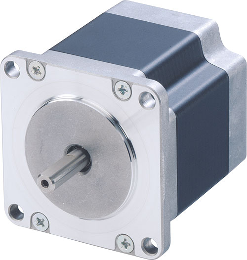
SERVO & STEPPER MOTORS IN CNC MACHINES


Computer Numeric Control (CNC) machines convert instructions into actions for controlling operating tools. Movement is triggered when alphanumerical codes are entered in a CNC machine, and they have several attached tools: laser cutters, routers, and cutting tips. Component design is automated using computer-aided design and computer-aided manufacturing programs. CNC machines use either servo or stepper motors, each having its own unique dis- and advantages.
Servo Motors
Servo motors transfer information to the CNC machine using closed-loop circuitry. A regular (DC or AC) motor is connected to an encoder with a fixed sensor: this encoder is why servo motors have high accuracy and resolution. The servo amp powers the motor and counts the steps made as well. The servo motor’s impressive torque-to-inertia ratio permits rapid load acceleration and, with light loads, efficiency may be as high as ninety percent.
The downside to using servo motors in CNC machines is they are more complicated to operate and typically more expensive than stepper motors. Servo motors are also more susceptible to damage from overheating and -loading because their ventilation system is easily contaminated at high speed. What’s more they require servicing once the brush has reached its two thousand-hour lifespan.
Stepper Motors
The stepper in stepper motor comes from the steps the motor makes, which are triggered by each signal pulse. Stepper motors are easy to operate, generally cost less than servo motors, and have a higher reported accuracy. Several loads can be driven without gearing due to stepper motors’ low-speed torque, allowing use of a timing belt and pulley reduction. Steppers usually use fifty to a hundred-pole brushless motors, whereas servo motors have only four to twelve poles. Steppers don’t require encoders.
Stepper control systems are optimal for applications requiring low-to-medium acceleration, high-holding torque, and the flexibility of open- or closed-loop operation.
Stepper motors are normally less efficient than servo motors. Smooth movement often necessitates microstepping because steppers are resonance prone. Their low torque-to-inertia ratio causes loads to accelerate less quickly. Steppers are louder than servo motors and, like servo motors, are prone to overheating at high performance. Lastly, stepper motors have a lower overall power output relative to their weight and size.

Thursday, November 1, 2012

THE ROBOTS ARE COMING — FOR YOUR GUITAR


It’s tedious to tune up your guitar before you play, to tune between songs, and to retune to, say, drop D for one song — only to retune again after the song is over a couple minutes later. If you’re playing in a band you have to make sure that everyone is tuned to exactly the same notes, which gets trickier when you add certain instruments to the mix (e.g., mixing equally tempered instruments with ones that are stretch-tuned).
If you like lighter strings or are a heavy-handed player or, worse yet, if you’re a heavy-handed player who likes lighter strings, you’ll know how quickly and unexpectedly your guitar can go out of tune. A perfect take in the studio amounts to nothing if you’re not in tune. And nothing is as irritating as going out of tune in the middle of a song.
If you have multiple guitars, electric and acoustic, chances are you have multiple tuners, perhaps a clip-on tuner for your acoustic and a pedal tuner on your board for you electric guitar, and maybe you still have that cheapo tuner you got when you bought first guitar. Maybe you even have a high-dollar strobe tuner for setting your intonation. Good pedal tuners are around a hundred bucks, and there are plenty that cost more than that. And heaven help you if you’re searching for that elusive perfectly accurate tuner pedal that doesn't color your tone and has a display that’s easy to read in low light or if you have bad G.A.S. Not only do you have to pay for the tuners themselves, but you've got to shell out for batteries, patch cables, replacement switches, etc.
You get the picture. Tuners are kind of a giant pain in the you-know-what.
Imagine being able to switch from standard tuning to open G to DADGAD in a matter of seconds. Think about how much time you spend tuning when you could be playing. Those times when your guitar goes out of tune in the middle of a song.... What if you could roll off your volume pot, strum all six strings at once, turn your volume back up, and launch into the solo in the middle of a gig?
Self-tuning “robot” tuners have been around for a few years. Maybe you've seen Gibson’s Robot Guitar or their other high-end guitars (e.g., the Dusk Tiger) with robotic tuners built into the back of the headstock, or maybe you've seen Jimmy Page’s Les Paul Goldtop with the costly Transperformance robotic tuning system, which requires heavily modifying your guitar. Soon enough robotic tuners are going to be available on the mass market, and you’ll be able to retrofit practically any guitar.
The catch is that they’re probably going to be expensive.
You don’t have to wait, though, and you don’t have to pay a premium. Students and do-it-yourselfers have been building robotic guitar tuners for years now, using affordable stepper motors and various components you can get from an electronics parts supplier. If you've got chops with a soldering iron, why not give it a shot yourself?

Tuesday, October 16, 2012

Buying a Home? Get an Inspection Camera

When you’re looking into purchasing a new house there are many things to consider. It is easy to miss the little things, such as inspecting the house. Sure a professional will come and do your home inspection for you. Keep in mind that these professionals can make mistakes as well, that’s why it is important to do your due diligence beforehand. To do a complete home inspection  you will need a tool that is incredibly helpful, that tool is the inspection camera.

Inspection cameras are used in a number of assorted applications, from automotive to forensic evidence. Now you’re probably thinking of the multiple ways you could use an inspection camera around the house. Has the cat lost his favorite toy? Use the inspection camera to check under the couch to locate the toy. On a more serious note, inspection cameras can be very useful for deciding if the price on the house is accurate.

Inspecting the pipes in a home is no easy task, they are often buried or located behind walls. There is a tool that can help you see these, that’s right, an inspection camera. The camera can view the outside of the pipes that are located behind walls. The camera can even go down into the drains to get a good view of what is happening inside. Making sure the pipes are working properly can save a buyer thousands of dollars in the end.

Lets face it, many of use are not going to be able to crawl through the ventilation system to see what type of shape it is in. An inspection camera can though. Vents can be long, which means an inspection camera extension may be something you will benefit from. These easily connect and disconnect from other inspection cameras making seeing deeper or farther quite easy.

Tuesday, October 9, 2012

Replacing Your Guitar’s Tone Pot


A common issue electric guitarists face is a tone potentiometer (hereafter tone pot) that, when turned, makes scratching and hissing noisesl. You should first try to clean a problematic tone pot with contact cleaner and, if that doesn’t fix the problem, chances are you have a bad tone pot that needs to be replaced.
Tone pots fine-tune your guitar’s tone by sharpening or deadening the output signal and over time wear, tear, and corrosion can damage the pot’s contacts, causing it to malfunction (i.e. causing scratching or other unwanted noises). On the bright side, replacing your tone pot is quite easy and straightforward, requiring only around fifteen minutes with your soldering iron or soldering station.
Step One
Disconnect your guitar from your amplifier and remove the cable. If your guitar has any active components, remove the batteries. You should never work on your electric guitar when the instrument is powered on because it can damage or ruin the guitar’s components. Remove the screws holding on the guitar’s back plate and then remove the plate.
Step Two
Remove the tone pot’s knob. Loosen the tone pot’s retaining nut with an adjustable wrench and unscrew the nut by hand, removing the nut and lock washer.
Step Three
Remove the tone pot from the guitar. Use a small piece of masking tape to protect each wire leading from the pot. It’s a good idea to write where each wire is soldered to the tone pot on these pieces of tape.
Step Four
Use wire cutters to cut the wire as close as possible to the old tone pot’s pins and remove the pot. Strip insulation from the end of each wire, twist the wire ends, and wrap them around the new tone pot’s pins using the notes you wrote on the masking tape in the previous step.
Step Five
Use your soldering iron or soldering station to solder the wires to the new tone pot’s pins, making sure to let the solder cool completely. Insert the new pot into your guitar and make sure your pot’s post fits and sits correctly and comes out the front of the guitar at the right angle.
Step Six
Next you’ll place the lock washer and retaining on the tone pot’s post’s threads and tighten the nut by hand. Finish by tightening the nut with the adjustable wrench.
Step Seven
Replace the knob on the tone pot’s post and secure the back plate back on the guitar and test out your new, noise-free tone pot.

Thursday, October 4, 2012

A Figurative Battle Royale in Stompbox Prototyping


Let’s discuss perfboard versus PCB versus stripboard (a.k.a. Veroboard) when you’re ready to transfer a stompbox circuit design — which should done on breadboard since it is reusable and easy to modify — to something more permanent to be enclosed in an effects pedal. (If you’ve got the parts to spare it’s a good idea to leave your design on the breadboard for visual reference and in order to take measurements with a digital multimeter if the permanent design requires troubleshooting.)
PCB Versus Perfboard
Nowadays the majority of stompboxes and amplifiers are assembled on printed circuit boards (PCBs), which are a piece of fiberboard or plastic on which all components are connected by internal conductive traces — you simply solder the components into their holes and the connections are good to go. If you’ve ever bought a stompbox kit, chances are it came with a PCB and a bag of parts, which is a quick and easy way to build an effects pedal.
The real benefit of using perfboard in our context is that you’ll develop a greater understanding of how circuits come together and work and you’ll make turning a simple schematic into a working circuit in future designs much, much easier. Perfboard consists of tiny, copper-lined holes in rows and, when designing circuits using perfboard, you’ll manually manually make all the circuit’s connections on the back of the board. Yes, perfboard is slower and more tedious than using a (so to speak) ready-made PCB, but the understanding you’ll gain by doing everything yourself will be invaluable in your subsequent stompbox designs.
Perfboard Versus Stripboard (Veroboard)
Stripboard, another alternative to PCB,  is similar to your average breadboard in that all the holes in a row are already connected. Designing a stompbox circuit with stripboard is also a great way to gain knowledge regarding the way circuits work during design. However, perfboard is more desirable than stripboard for novice stompbox builders because it’s considerably easier to find and a little more demanding and time-consuming, which will lead to a more thorough understanding of stompbox design that will lodge itself in the back of your brain as you build your next effects pedal.
Note that the preferability of perfboard over stripboard or PCB is aimed at novice pedal builders who may not have an established grasp of/experience in circuitry. When it comes to newbie stompbox designers, perfboard is the hands down winner of the figurative battle royale in stompbox prototyping due to the greater understanding of circuit designs it affords.

Wednesday, October 3, 2012

Stompbox Design with Solderless Breadboards


Let’s say you’ve come up with a novel new circuit for the next Tubescreamer, Ibanez AD-80 delay, etc. that you just know guitarists around the globe will be lining up for one day. You thoughtfully and carefully design your pedal, build it with the finest NOS components from some abandoned Soviet warehouse, meticulously solder your circuit with your high-dollar solder iron or soldering station, and you fire it up for the first time . . . and it doesn’t work, or it doesn’t sound quite how you expected it to.
That’s why solderless breadboards (henceforward called SoBs) are invaluable to stompbox builders: they allow you to quickly and easily design, tweak, and test a circuit without committing to a permanent, finalized design. SoBs come in barebones versions as well as more complex units with built-in power supplies and digital multimeters and mounting brackets and the kitchen sink.
How SoBs Work
Each hole in the SoB’s plastic rail contains a spring-loaded contact that grips the inserted component’s lead while letting you easily remove it. Each column of five holes is internally connected. You can test this by inserting short lengths of 22 or 24 AWG wire into any two holes in a column and measuring between the wires with your digital multimeter in the continuity position (or the lowest resistance scale if your DMM doesn’t have the continuity position).
SoBs have busses, which are a row of horizontally-connected holes that provide a common ground and allow you to distribute power to the necessary points in the circuit. Some SoBs have busses that are connected all the way across, while other are split in the middle — meaning you’ll have to connect the halves for full-length continuity.
If you’re a stompbox builder, do yourself a favor and get yourself an SoB; in addition to being reusable, they’ll really speed up stompbox circuit design, testing, and tweaking before you put time and money and elbow grease into your prototype pedal.

Monday, September 24, 2012

Five Reasons Everyone Needs an Inspection Camera

Many people don’t think about purchasing an inspection camera, many of us may think we don’t really need one. For years these tools were priced quite high and not to mention were very large. Over the years the size and price inspection cameras reduced significantly. Now you can purchase a good quality inspection camera for $100-150. At these prices this is a tool every home should have. Here are a few reasons why you should get yourself one,

1) Checking the walls - Looking inside your walls makes buying a inspection camera completely worthwhile. Often people need to cut into walls or guide cable through and you may not know what is on the other side. One false cut can cause incredible damage to anything that can be within the wall. With an inspection camera the user will be able to check behind the wall to see where to make proper cuts.

2) Seeing under the car - Have something leaking under the car? Hearing a rubbing noise? Grab your inspection camera, and investigate. No more rolling around the ground trying to get an uncomfortable look under the car.

3) What’s in the drain? - Do you have kids around the house and constantly experiencing drains clogging? Before you take that pipe apart or call in a professional to begin snaking the drain grab your inspection camera and give it a look.

4) See into vents - The vents in our houses are something that go unnoticed for years. Not until there is an issue to we really put much thought into them. With an inspection camera you can quickly give you a clear display of what is going on throughout your home.

5) They’re handy - An inspection camera can make everyday task much easier. For instance, where did the dog toy go? Grab the camera and check under furniture. Did I drop a sock behind the washer machine? There’s an easy way to check, use your inspection camera.

The uses for inspection cameras are endless and priced under $200 it is an excellent investment. The are small and lightweight which makes transporting them easy. Their size makes them great for storing in the garage, and don’t take up much room if left in the car. With so many uses, every home should have one.

Tuesday, September 18, 2012

Conductive Pen for Electronic Fun

Conductive pens are very popular among hobbyists and electronic repair experts. Most commonly these pens are used for printed circuit board repair, however they have many more uses. Often hobbyists will use the conductive pen for in home projects that require linking electric currents. As the video below shows, there are many interesting projects any beginner can do with a conductive pen and some creativity.

Monday, September 17, 2012

What Good is a Breadboard?


Breadboards are reusable solderless circuit boards (PCBs) with electrical contacts arranged in a number of rows and columns. Because breadboards have built-in electrical contacts, you don’t need nearly as many wires as you would have had to use without the circuit board, which consolidates what could’ve been a rat’s nest of electronic components and wires into a neatly arranged circuit. Your components are inserted across tracks and, if required, tracks can be joined with wires. The most common breadboard used today, with its white plastic and pluggable (solderless) contacts, was designed in 1971 by Ronald J. Portugal.
Most often breadboards (also known as plugboards) are used to construct a temporary circuit for prototyping or general experimentation; since breadboards don’t require solder, you can quickly and easily assemble and disassemble a circuit design . . . and you can use the same breadboard later for another design. These features make breadboards especially appropriate as school laboratory equipment, allowing students to expand their knowledge of electronics by building circuits from schematics — a type of procedural knowledge — and this sort of hands-on project will help students retain what they’ve learned.
Breadboards are also commonly used by hobbyists and professionals looking to test components or when designing/building complex circuits, because these solderless boards are “lower stakes” than stripboards (veroboards), which are used to build permanent soldered prototypes or one-offs and which can’t be reused without going to a whole lot of trouble. Since these breadboards are reusable, they are an economical choice for those who frequently build prototypes or experiment with circuitry.
So, as you can see, breadboards do a whole lot of good in the classroom and in the hands of hobbyists and professionals who need an easy, economical way of experimenting and designing complicated circuit boards.

Wednesday, September 12, 2012

Full Value from a Fluke Tool

No matter what type of tool you are using it is important to get the full use out of the unit. With Fluke items users will rest assure their instruments are working at the optimum performance, however, not all users know how to check this.

To assist in consumers operating their tools, such as digital multimeters, Fluke has begun putting together free webinars. These are designed to help users better understand the Fluke products they have purchased. The webinars are under an hour long and give useful insight into how the tools operate.

An example of a recent webinar would be on Electrical Energy Efficiency Measurement Principles, where a Fluke specialists describes features of the Fluke digital multimeters. The webinar also mentions the energy waste that is associated with poor power quality which can be caused by an unbalance and harmonic issues.

Webinars are scheduled often so it is important to check back with Fluke often for dates and times. The webinars are recommended for all users, regardless of your level of expertise. Check the site to find out more about the free webinars.


Friday, September 7, 2012

Types of Oscilloscope Waveforms


Most waveforms on digital storage oscilloscopes are easy to identify: there are sine, square, rectangular, triangle, sawtooth, step-, and pulse-shaped waves.
Good Ol’ Sine Waves
Sine waves are the fundamental waveform because of their prevalence and their harmonious mathematical properties. (It’s the same sine wave you had to learn in high school math class.) The voltage from your wall’s outlet makes a sine wave. Test signals from a signal generator’s oscillator circuit make sine waves. AC power sources make sine waves. You get the picture.
Then there’s the damped sine wave. You’re likely to see this in a circuit that oscillates while winding down over time. Whereas an ordinary sine wave rolls up and down with regularity, a damped sine wave rolls up and down while getting decreasing in amplitude — the wave gets closer to zero the longer it goes on.
Square and Rectangular Waves
Square waves are almost as common as sine waves. A square wave is, in essence, a voltage that turns on and off — or abruptly alternates between high and low — at recurring intervals. Television, radio, and computer circuitry frequently uses square waves for timing signals.
Rectangular waves are similar to square waves, save for the fact that the high and low intervals aren’t equal lengths.
Sawtooth and Triangle Waves
Linearly controlled voltages result in sawtooth and triangle waves on the digital storage oscilloscope. The voltage levels of these types of waves transition at a constant rate, and these transitions are called “ramps”.
Step- and Pulse-Shaped Waves
Signals like steps or pulses that occur just once are called single-shot or transient signals. A step represents a sudden change in voltage — it’s what you’d see if you flipped a power switch. If you flipped that power switch on and then off, then you’d get a pulse.
Computer components communicate with one another using pulses. Pulses are common in x-ray and communications equipment as well.


Saturday, August 25, 2012

Reducing the Heat of a Stepper Motor

Heating can be very common within stepper motors, some heating is normal, however this heat should be kept at a safe level. Why does the stepper motor heat up? Often this happens due to the internal core and windings of the motor. The resistance of the winding will cause power loss, which is often called copper loss. If the current is not a standard DC it may also experience harmonic loss.

The stepper motor may also have heat changes in response to the speed of the motor. The motor will often maintain constant speed under low speeds that are consistent. If the stepper motor is subjected to various speeds the copper loss may increase and heat the motor.

To reduce the step motor from heating the easiest thing to do is reduce the copper loss. This is done by reducing the resistance and the current, the easiest way to do this is to find a motor with a low resistance and current. Keep the motor running at consistent speeds, and make sure you select the proper step motor for your application.

Tuesday, August 21, 2012

Fluke Donates Digital Multimeters

This past June the Fluke Company made a generous donation of twelve new digital multimeters to Everett Community College located in Everett, Washington. The company is based out of Everett, Washington and has made multiple contributions to institutions in the past. The multimeters were sent to the engineering department of the community college and will be used in a number of different class related projects.

Engineering instructor, Matthew Parsons, of Everett Community College mentioned it is more useful to have a digital multimeter in an electrical engineering class than a pencil. The multimeters are used to measure functions such as voltage, current, temperature, and resistance.

Donations like these help drive students to pursue careers within engineering, and possibly with the Fluke. Fluke, being a leader in test equipment and software, realizes it is important to provide the youth with quality tools. The company knows the products are going to good use.

Monday, August 13, 2012

Preparing to Solder

Soldering is a tool that is used by professionals and hobbyists alike. It is defined as joining metals by fusing the alloys which have low melting points. This type of skill is often used in electrical and electronic work, it is a skill that is easy to practice and is very useful. Use the following tips to prepare yourself for soldering.

Before you begin soldering it is important to “tin” the tip of the soldering iron. This is coating the soldering iron tip with a coat of solder to aid in heat transfer. Next will be time to warm up the soldering iron. Make sure the iron heats up completely, this is very important with new soldering irons, since there may be a layer of coating on the tip to prevent corrosion.

The next step is to have an open, clutter free work area. It is important to have proper air flow, no loose clothing on, and a moistened sponge for cleaning the soldering tip. Now you will want to coat the tip in solder, making sure to coat the entire tip. Keep in mind you will be using a good amount of solder so keep more close and handy. Once the soldering tip has been coated with solder wipe the tip with the wet sponge to remove any flux residue. This is best done quickly so the residue has no time to harden and stick to the solder tip.

Tinning must be done every time the soldering iron tip is changed or a new one is being used. This will make it easier for heat to transfer from the iron to the solder. Soldering will go quicker and you will be much more precise.

Thursday, August 2, 2012

Fluke wins 2012 Gold IDEA Award for Clamp Meter family product design

PRNewswire has reported the Industrial Designers Society of America(IDSA) has honored Fluke Corporation with a Gold Award in its International Design Excellence Awards(IDEA) program. This international competition honors design excellence in strategy, products, concepts and research, and more. The new 37x/38x clamp meter from Fluke won the award in the Commercial and Industrial Products category.

Fluke was created in 1948 and has been a leader in growing a technology market that requires troubleshooting in service and manufacturing industries. Fluke products are used in a number of manufacturing plants, offices, hospitals and homes of hobbyists. Professionals in many fields, including; electricians, plant engineers, and HVAC technicians, use Fluke products including digital multimeters, and variances of the clamp meter.

The Fluke clamp meter answers the ergonomic issue clamp users have had for years. How to read the display easily, while positioning the clamp. Fluke has fixed this problem by decoupling the display from the meter making it easier to read. The new clamp meter is sure to be a great addition to many professionals, in many different fields.

Friday, July 27, 2012

How to Use a Coaxial Cable Tester

Having a coaxial cable tester handy can make checking insulation losses and crossed wiring quick and simple. These tools are very easy to operate and understand, which makes them very popular among professionals and amateurs alike. This tutorial will show users how to use a coaxial cable tester.

Step 1 - The first thing to do is remove all cables from any source of electrical power. Make sure the cables are not laying near other cables that may be conducting electrical signals. A stray voltage signal can give false information and compromise your results.

Step 2 - Before we begin it is important to inspect the cable for any damages. By doing this you may save much time and money, especially if the cable is already damaged and unusable.

Step 3 - Now it’s time to get started testing, first short the conducting ends of the cable to an earth ground. We will drain any errant static voltage, but connecting the other end of the clip to a cable metal pin.

Step 4 - Attach the cable into the tester, this can be use any adapter that will be compatible with the coaxial cable tester and cable. Finally it is time to turn the tester on. Select the type of test you want to conduct on the tester, push the button, and wait for your results.

A coaxial cable tester can help users identify cables that need to be decommissioned or where a connection might be bad. It is always important to test your cables before installing, you may never be able to tell what is wrong with a cable until it is tested.

Monday, July 16, 2012

Removing a SMD with a Solder Iron

George from Circuit Specialists Inc. shows us how to remove a surface mount device from a printed circuit board. In the video he shows how to use the product Chip Quik, and it is all done using a soldering station. For a video how-to request, please visit our website and contact us.

Thursday, June 28, 2012

Valuable Solderless Breadboards

In most cases the uses for a solderless breadboard is to test new designs that do not require soldering. Since no soldering is needed these are excellent for experimenting with. Since the solderless breadboards are reusable, they are often used in classrooms or other learning facilities. There are plenty of projects that can be done using solderless breadboards and a popular one is building a LED panel. Few parts are needed, and the solderless breadboard can be used over and over with similar projects.

Wednesday, June 27, 2012

Introduction to the PCB Cutter

Our product guru, George, takes the time to show us the ins and outs of the new PCB Cutter. The cutter is machined from durable steel and features a plastic guard to prevent accidental cuttings. See the item in use before making the purchase, you'll be pleasantly surprised with the results.


Tuesday, June 26, 2012

Quality Coaxial Cable Tester

Circuit Specialists has long been know for providing excellent test equipment and their coaxial cable tester is no exception.  I have used this tester when installing cable TV, cable phone and internet connections around my home.

When my local Cox Cable installer came to my house initially to run a new main cable, i noticed he was using at test unit similar to this one.  My guess is the unit he was using cost several times more then this high quality device.

In closing, Circuit Specialists continues the tradition of providing high quality test equipment like multimeters and oscilloscopes at excellent prices.  Oh, and the support can't be beat!


Monday, June 18, 2012

Digital Panel Meters Explained

What exactly is a panel meter? In the simplest of terms a panel meter is a display instrument that shows the input signal in an analog or digital form. In many of today’s applications digital panel meters are often the most popular. They are easy to read and are very durable which makes them easy for hobbyists to work with. Digital panel meters can be used to measure voltage, current, pressure, volume or temperature, another reason why they are commonly used. Circuit Specialists Inc., provide LCD panel meters that offer a clear display.


Thursday, June 7, 2012

Using a Digital Panel Meter (DPM) to monitor the 12 V battery system in a vehicle (car, truck, boat motorcycle, etc.)

I get a fair number of questions from customers concerning how to connect a digital panel meter (DPM) to measure the 12 V electrical system in a vehicle. I have prepared this drawing showing the required connections along with a parts list indicating Circuit Specialists part numbers that are required to perform this operation.

Since the power for the DPM is to be derived from the same electrical system that is being monitored, this will require a DPM that uses a COMMON GND system. These include the PM-1029B and the PM-128E and PM-128E-BACKLIT. Other models with a common ground connection will also work but require additional components so I prefer the three models listed above.

All of the common ground units require 5 V power to operate the digital panel meter so some method of reducing the 12 V from the vehicle’s electrical system is required. I recommend using a 5 V regulator (such as the 78L05 or 7805) along with a small capacitor (such as 21ET100 ceramic disc) to supply the required power to the DPM.

The attached drawing shows the connections for the PM-1029B DPM and is similar to the PM-128E connections but there are differences in the jumper settings for each meter. If using the PM-128E (or PM-128E-BACKLIT) DPM, the DC and the J1 and J2 jumpers must be set correctly.

Click Image to Enlarge

Wednesday, June 6, 2012

What Are Digital Panel Meters

Digital panel meters are used to measure and show electrical variables. These variables may include voltage monitoring to current, flow, speed, and much more. The digital panel meters are fitted with a bright LED or LCD display for easy viewing. Digital panel meters are often used in replacement of analog panel meters since they are much more accurate and have a faster response time. Many of these newer types of meters will have additional features that may include alarm options, or on/off switches that control the process unit.