Friday, September 7, 2012

Types of Oscilloscope Waveforms


Most waveforms on digital storage oscilloscopes are easy to identify: there are sine, square, rectangular, triangle, sawtooth, step-, and pulse-shaped waves.
Good Ol’ Sine Waves
Sine waves are the fundamental waveform because of their prevalence and their harmonious mathematical properties. (It’s the same sine wave you had to learn in high school math class.) The voltage from your wall’s outlet makes a sine wave. Test signals from a signal generator’s oscillator circuit make sine waves. AC power sources make sine waves. You get the picture.
Then there’s the damped sine wave. You’re likely to see this in a circuit that oscillates while winding down over time. Whereas an ordinary sine wave rolls up and down with regularity, a damped sine wave rolls up and down while getting decreasing in amplitude — the wave gets closer to zero the longer it goes on.
Square and Rectangular Waves
Square waves are almost as common as sine waves. A square wave is, in essence, a voltage that turns on and off — or abruptly alternates between high and low — at recurring intervals. Television, radio, and computer circuitry frequently uses square waves for timing signals.
Rectangular waves are similar to square waves, save for the fact that the high and low intervals aren’t equal lengths.
Sawtooth and Triangle Waves
Linearly controlled voltages result in sawtooth and triangle waves on the digital storage oscilloscope. The voltage levels of these types of waves transition at a constant rate, and these transitions are called “ramps”.
Step- and Pulse-Shaped Waves
Signals like steps or pulses that occur just once are called single-shot or transient signals. A step represents a sudden change in voltage — it’s what you’d see if you flipped a power switch. If you flipped that power switch on and then off, then you’d get a pulse.
Computer components communicate with one another using pulses. Pulses are common in x-ray and communications equipment as well.


Saturday, August 25, 2012

Reducing the Heat of a Stepper Motor

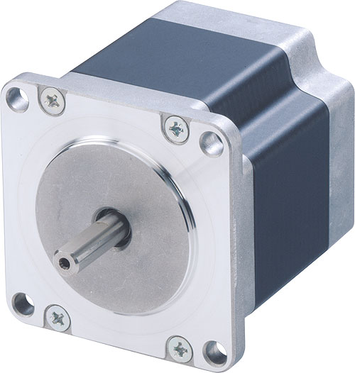
Heating can be very common within stepper motors, some heating is normal, however this heat should be kept at a safe level. Why does the stepper motor heat up? Often this happens due to the internal core and windings of the motor. The resistance of the winding will cause power loss, which is often called copper loss. If the current is not a standard DC it may also experience harmonic loss.

The stepper motor may also have heat changes in response to the speed of the motor. The motor will often maintain constant speed under low speeds that are consistent. If the stepper motor is subjected to various speeds the copper loss may increase and heat the motor.

To reduce the step motor from heating the easiest thing to do is reduce the copper loss. This is done by reducing the resistance and the current, the easiest way to do this is to find a motor with a low resistance and current. Keep the motor running at consistent speeds, and make sure you select the proper step motor for your application.

Tuesday, August 21, 2012

Fluke Donates Digital Multimeters

This past June the Fluke Company made a generous donation of twelve new digital multimeters to Everett Community College located in Everett, Washington. The company is based out of Everett, Washington and has made multiple contributions to institutions in the past. The multimeters were sent to the engineering department of the community college and will be used in a number of different class related projects.

Engineering instructor, Matthew Parsons, of Everett Community College mentioned it is more useful to have a digital multimeter in an electrical engineering class than a pencil. The multimeters are used to measure functions such as voltage, current, temperature, and resistance.

Donations like these help drive students to pursue careers within engineering, and possibly with the Fluke. Fluke, being a leader in test equipment and software, realizes it is important to provide the youth with quality tools. The company knows the products are going to good use.

Monday, August 13, 2012

Preparing to Solder

Soldering is a tool that is used by professionals and hobbyists alike. It is defined as joining metals by fusing the alloys which have low melting points. This type of skill is often used in electrical and electronic work, it is a skill that is easy to practice and is very useful. Use the following tips to prepare yourself for soldering.

Before you begin soldering it is important to “tin” the tip of the soldering iron. This is coating the soldering iron tip with a coat of solder to aid in heat transfer. Next will be time to warm up the soldering iron. Make sure the iron heats up completely, this is very important with new soldering irons, since there may be a layer of coating on the tip to prevent corrosion.

The next step is to have an open, clutter free work area. It is important to have proper air flow, no loose clothing on, and a moistened sponge for cleaning the soldering tip. Now you will want to coat the tip in solder, making sure to coat the entire tip. Keep in mind you will be using a good amount of solder so keep more close and handy. Once the soldering tip has been coated with solder wipe the tip with the wet sponge to remove any flux residue. This is best done quickly so the residue has no time to harden and stick to the solder tip.

Tinning must be done every time the soldering iron tip is changed or a new one is being used. This will make it easier for heat to transfer from the iron to the solder. Soldering will go quicker and you will be much more precise.

Thursday, August 2, 2012

Fluke wins 2012 Gold IDEA Award for Clamp Meter family product design

PRNewswire has reported the Industrial Designers Society of America(IDSA) has honored Fluke Corporation with a Gold Award in its International Design Excellence Awards(IDEA) program. This international competition honors design excellence in strategy, products, concepts and research, and more. The new 37x/38x clamp meter from Fluke won the award in the Commercial and Industrial Products category.

Fluke was created in 1948 and has been a leader in growing a technology market that requires troubleshooting in service and manufacturing industries. Fluke products are used in a number of manufacturing plants, offices, hospitals and homes of hobbyists. Professionals in many fields, including; electricians, plant engineers, and HVAC technicians, use Fluke products including digital multimeters, and variances of the clamp meter.

The Fluke clamp meter answers the ergonomic issue clamp users have had for years. How to read the display easily, while positioning the clamp. Fluke has fixed this problem by decoupling the display from the meter making it easier to read. The new clamp meter is sure to be a great addition to many professionals, in many different fields.

Friday, July 27, 2012

How to Use a Coaxial Cable Tester

Having a coaxial cable tester handy can make checking insulation losses and crossed wiring quick and simple. These tools are very easy to operate and understand, which makes them very popular among professionals and amateurs alike. This tutorial will show users how to use a coaxial cable tester.

Step 1 - The first thing to do is remove all cables from any source of electrical power. Make sure the cables are not laying near other cables that may be conducting electrical signals. A stray voltage signal can give false information and compromise your results.

Step 2 - Before we begin it is important to inspect the cable for any damages. By doing this you may save much time and money, especially if the cable is already damaged and unusable.

Step 3 - Now it’s time to get started testing, first short the conducting ends of the cable to an earth ground. We will drain any errant static voltage, but connecting the other end of the clip to a cable metal pin.

Step 4 - Attach the cable into the tester, this can be use any adapter that will be compatible with the coaxial cable tester and cable. Finally it is time to turn the tester on. Select the type of test you want to conduct on the tester, push the button, and wait for your results.

A coaxial cable tester can help users identify cables that need to be decommissioned or where a connection might be bad. It is always important to test your cables before installing, you may never be able to tell what is wrong with a cable until it is tested.

Monday, July 16, 2012

Removing a SMD with a Solder Iron

George from Circuit Specialists Inc. shows us how to remove a surface mount device from a printed circuit board. In the video he shows how to use the product Chip Quik, and it is all done using a soldering station. For a video how-to request, please visit our website and contact us.