Thursday, April 11, 2013

Frequency Counter Primer


Frequency counters are easy to use: simply turn on the device and apply the signal to the input. You can use your frequency counter and timer to measure a variety of signals including digital logic signals, radio frequency, and even microwaves. Because of improvements in technology, frequency counters and timers enable you to measure time intervals and frequency, which have an inverse relationship.
You’ll need to apply the signal to the input to measure a time interval or frequency. The next step will be to select the timebase interval, which commonly has the options of point one, one, and ten second(s). These options refer to the time over which the frequency counter gate opens and passing pulses are counted; for example a gate time of one second will count one million pulses for a one megahertz signal or, if five pulses are counted with a gate time of one second, the frequency will be five hertz.
Your frequency counter counts the transition every time the signal passes in the positive direction through the device. More pulses are counted at higher frequencies as you can see from our the example above in which five pulses are counted.
You’ll get more accurate results with longer gate times. Let’s use the previous example with a gate time of point one second for five pulses and a fifty hertz signal. The handheld frequency counter can’t tell the difference between a fifty hertz and fifty-five hertz signal. To get a more accurate reading you can use a one second gate time, thus enabling fifty-five counts for a fifty-five hertz signal.
While longer gate times improve accuracy, your choice of gate time will normally depend on how quickly you need updates for the frequency. Despite the benefits to accuracy longer gate times can slow testing to too great an extent. Because of these tradeoffs in time versus accuracy, you’ll usually use shorter gate times unless you need a high level of accuracy for a particular test.

Wednesday, April 3, 2013

Multimeter Features Guide


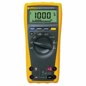
There are a number of different features that differ from one multimeter to the next, some of which you’ll often use and others you may never use.
The most important feature is continuity, which allows you to test whether two things are electrically connected. Continuity testing with a peizo buzzer enables you to determine if your soldering is good, a wire is broken in the middle, and something isn’t connected in addition to allowing you to reverse-engineer or verify a design to a schematic.
Some other important features are resistance testing down to ten ohms or lower and up to one megaohm or higher, direct current voltage testing down to one hundred millivolts or lower and up to fifty volts, alternate current testing down to one volt and up to two hundred volts, and diode testing.
Because it’s easy to forget to turn off your multimeter’s power, auto-off is a great feature to have, which you rarely see on budget multimeters. Regardless of this feature you should get in the habit of turning off your multimeter after you finish using it.

If you know how to use it autoranging is a helpful feature and, typically, autoranging multimeters are of higher quality and have more features than simpler multimeters. Keep in mind that with some systems the current or voltage will be too sporadic for the autorange feature to keep up. Some users dislike autoranging because it slower and less precise.
Other optional but useful multimeter features are alternate and direct current testing, a stand for keeping the multimeter upright, a hold function to keep the maximum value on the screen enabling you to use the probes without staring at the screen, and common battery types (such as a nine volt or AAs).
Back-lit LCD multimeters are nice, but chances are you won’t be measuring circuits in the dark. If you need a multimeter that is visible in low light then by all means look for a back-lit model.
You don’t really need fancy probes for you multimeter — just some sturdy, reasonably-priced ones. Your leads will break down over time, generally at the flex point; however, probes are relatively inexpensive, so when you do break a probe, which you eventually will with enough use, you’ll be able to replace it for around five dollars.
Some features you’ll seldom use include a frequency counter, capacitance testing, inductance testing, duty cycle, transistor beta meter, and temperature probe.

Wednesday, March 20, 2013

DIGITAL MULTIMETER TEST ENVIRONMENTS


While digital multimeters are still commonly used in benchtop testing, there are now a number of interconnect options for system integration; e.g., some multimeters offer hobbyists and engineers alike USB interfaces and general purpose interface buses for control via PC using test commands. Certain LabVIEW drivers allow one to integrate one’s multimeter into a larger test system. Then there are front-panel thermocouple inputs which allow one to connect directly to many prevalent temperature measurement sensors.
Indicating a multimeter’s susceptibility to noise, digital multimeters have specifications for normal mode rejection ratio and common mode rejection ratio with common values of over sixty decibels and one hundred twenty decibels. The noise produced by one’s multimeter is particularly important when measuring low signal levels, and electromagnetic interference standards influence compliance levels.
Because of its influence on throughput, a digital multimeter’s measurement speed — typically displayed as readings per second at a specific resolution level — is especially important in production environments.
A number of modern multimeters have resolution levels that one can program, thus simplifying balancing speed and accuracy. The integration period, which is the amount of time when a signal is sampled by the multimeter’s analog-to-digital convertor, is typically displayed in number of power line cycles; number of power line cycles made up of integer multiples — one, five, ten, etc. — will reduce the fifty/sixty hertz line pickup, which is the most common type of noise. One will have greater noise reduction with a larger number value with the caveat that measurementS will take longer to complete.
The number of analog-to-digital conversions averaged for each reading, or digital filtering, can stabilize readings with excess noise but, again, this will slow measurement times.
One’s multimeter measures internal voltages in order to retain stability and accuracy with temperature changes over time when a multimeter’s autozero is used, but overuse of autozero will negatively impact the multimeter’s reading rate. Throughput can be increased by disabling autozero, performing it at certain intervals, or programming the multimeter to use autozero during the load/unload cycle.
Speed specifications like range changing speed, autorange time, and function changing rate might also affect throughput, and hardware triggers are generally faster than software triggers. Certain digital multimeter’s have a microprocessor dedicated to triggers which can significantly reduce latency. Setting or response time is also important when one is testing high-impedance devices.
Speedy and accurate switching is notably important in production test environments, because hundreds or even thousands of devices have to be tested every shift, and newer models support hundreds of multiplexer channels or thousands of matrix crosspoints.

Wednesday, March 13, 2013

PRINTED CIRCUIT BOARD MATERIALS & APPLICATIONS


Using different printed circuit board (PCB) materials will result in different circuit board specifications and prices with regard to PCB prototyping and production. Certain one- or two-layer boards need what is known as pre-preg core — which is a material made from fine layers of fiberglass that is pre-impregnated with a bonding agent or metal core — or several layer boards using two or more kinds of cores for construction. Board thickness varies from a few millimeters thick, for flexible boards, to as much as a quarter inch thick, for heavy burn-in boards. Core materials typically resemble thin double-sided boards with dielectric materials (e.g. fiberglass) as well as copper foil on each side, and they generally come in predetermined thicknesses.
FR4 is the most commonly used type of substrate for circuit boards and is made from a glass-fiber epoxy laminate. FR4 has higher temperature coefficients and lower dielectric constants — e.g. FR4 has a starting thermogravimetry (TG) of one hundred forty degrees Celsius, FR4-06 has a TG of one hundred seventy degrees, and the temperature increases as the family number increases.
Prototypes using metal core, which has impressive heat elimination, are quite popular for light emitting diode (LED) circuit boards. The metal core is an efficient heat sink and keeps the LEDs operating at safe temperatures. One section of a metal core printed circuit board prototype has a metal base, a non-conductive layer (usually aluminum), a copper circuit layer, integrated circuit (IC) components, and a solder mask.
Polyimide printed circuit board prototypes, which are tougher than FR4, can sustain significantly hotter temperatures, making them perfect for most electrical insulation applications. The polyimide is made up of a silicone adhesive and a polyimide film designed to withstand higher temperatures and will protect edge connectors, gold edge fingers (during wave soldering), and reflow soldering (during circuit board assembly). Polyimide can be distinguished from other boards by its distinctive brown color.
Polytetrafluoroethylene (PTFE) or woven glass base circuit board materials necessitate special drilling procedures because Teflon is much softer than, e.g., FR4. These types of materials are far more common than they once were. PTFE/woven glass base materials provide rapid growth of applications operations and easily meet high-frequency demands, and they consistently perform well.
You can also use Arlon materials for longer operating lives at high temperatures, or Isola range circuit board prototypes for broadband circuit designs requiring faster signal speed or better signal fidelity.

Wednesday, March 6, 2013

USING AN OSCILLOSCOPE ON AUTOMOBILES


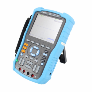
A digital storage oscilloscope makes it easy to visualize alternating current electrical signals in an automobile. Oscilloscopes have several electrical inputs and control knobs as well as a liquid crystal display (LCD) screen for displaying the signal.
Generally automotive oscilloscopes are used in manufacturing applications by engineers to set electrical signals to the right form. They are also frequently used in garages by mechanics to test the engine’s components for faults. In addition oscilloscopes are increasingly being used by do-it-yourselfers and those looking to make their own automotive repairs. Some examples of electrical signals that one might observe with an oscilloscope are the ignition sequence and the throttle position sensor’s output.
Let’s take a look at how you can use your oscilloscope on your automobile.
Step One
First you’ll need a coaxial cable, which you will connect between the car’s output that you are testing and one of the oscilloscope’s inputs. Most simple digital storage oscilloscopes have two inputs, typically labelled A and B. It doesn’t matter which input you use. You’ll switch the input on by, e.g., pressing either the A or B button.
Step Two
Next you’ll alter the volts/division control in order to change the vertical scale as well as the number of volts for each division. You won’t be able to see the electrical signal clearly on your oscilloscope’s display  until you’ve adjusted the settings appropriately.
Step Three
Now it’s time to adjust the oscilloscope’s time/division (also known as timebase) control which changes the number of times each horizontal division is shown. When you know the electrical signal’s frequency you can accurately calculate the time/division. The time for a single period is T=1/f (with f being the frequency). Then you’ll set the time/division to the calculated value using the equation above.
Step Four
The last step is to adjust the vertical position control, which will move the signal up or down on the oscilloscope’s display. Your goal is to center the signal.
By following these four simple steps you can use your digital storage oscilloscope to observe your automobile’s electrical signals.

Wednesday, February 27, 2013

ARBITRARY WAVEFORM GENERATOR SIGNALS

Used to test various circuit topologies, an arbitrary waveform generator (or AWG) can be used as general-purpose function generator as well as a waveform generator. Let’s first address the difference between a signal generator, function generator, and an arbitrary waveform generator.
Signal generators produce high-fidelity sine wave signals that range from low frequencies to many gigahertz (GHz). Features of signal generators include attenuation, modulation, and sweeping.
Function generators are lower-frequency instruments which produce sine, square, pulse, triangle, and ramp waveforms from direct current up to a few megahertz (MHz) and usually cover a wide range of voltage.
Arbitrary waveform generators, which we’ll be focusing on below, are high-flexibility signal sources that can generate any arbitrary waveform constructed from point-by-point in digital memory, and these constructed waveforms are converted into analog signals with the AWG’s digital-to-analog converter (DAC), which operate at clock rates up to a few gigahertz (GHz). Because AWGs have built-in algorithms that generate standard functions, they can stand in as an ordinary function generator.
Types of Arbitrary Waveform Generator Signals
There are four categories of waveforms that an arbitrary waveform generator can create: standard and advanced functions, arbitrary waveforms, and waveform sequences. The standard functions category consists of pulse, ramp, sine, square, and triangle waveforms which are used in such applications as baseband, audio, sonar, ultrasound, and video components as well as circuits. Frequency response characterization, digital logic generation, device linearity characterization, and direct current-offset signal generation tests can be performed with an arbitrary waveform generator.
The majority of arbitrary waveform generators feature advanced functions including multi-tone, cardiac, noise, and much more that are used by specific industries for unique applications — e.g., cardiac and haversine signals are commonly used in medical device tests. Due to the abrupt transitions in the signal, standard pulse waveforms excite the device under test with extensive harmonic content; and other kinds of pulse waveforms have smooth transitions which shape the harmonic content for certain applications. Some examples are sinc and exponential pulses.
Sinc pulses, which are shaped with bandwidth-limited frequency spectrums, are used to characterize or excite communications channels that have limited bandwidth capability. Exponential pulses can simulate various physical phenomena, e.g., a resistor-capacitor charging circuit.

Wednesday, February 20, 2013

DIGITAL STORAGE OSCILLOSCOPES: CHOOSING THE RIGHT BANDWIDTH


Because there are hundreds of models available with different specifications at a wide variety of prices, choosing the right oscilloscope can be intimidating and confusing for many engineers and technicians. In this article we’ll look at a few aspects of digital storage oscilloscopes that are of particular importance in order to help you avoid a costly mistake.
Some things to consider before we get into the specifics of bandwidth are: where you’ll be using the oscilloscope, how many signals you’ll need to measure at one time, the minimum and maximum signal amplitudes you’ll be measuring, the highest frequency signal you’ll potentially measure, whether your signals are repetitive or single-shot, and whether you need to view signals in the frequency domain (i.e. spectrum analysis) and the time domain simultaneously.
Bandwidth
Bandwidth is the maximum signal frequency that can pass through the front-end amplifiers and the oscilloscope's bandwidth must be higher than the maximum frequency you’d like to measure. However, sufficient bandwidth isn’t the only consideration when making sure that a digital storage oscilloscope can capture a high-frequency signal accurately.
Oscilloscope manufacturers seek a certain type of frequency response when designing their instruments and this response is called the maximally flat envelope delay, or MFED. This type of frequency response provides superb pulse fidelity with very little undershoot, overshoot, and ringing. Because a digital storage oscilloscope is made up of amplifiers, attenuators, analog-to-digital converters, interconnects, and relays, maximally flat envelope delay response cannot be entirely realized — think of it more as an ideal.
Please note that the majority of oscilloscope manufacturers define bandwidth as the frequency at which a particular sine wave signal will be attenuated to seventy-one percent of its actual amplitude, i.e. the trace will be twenty-nine percent in error of the input signal.
Your signal will contain high-frequency harmonics if your input signal isn’t a pure sine wave; e.g. a twenty megahertz signal viewed on a twenty megahertz bandwidth oscilloscope will show up as a distorted and attenuated waveform. A good rule of thumb here is choosing an oscilloscope with a bandwidth five times higher than the maximum frequency signal you’d like to measure. The caveat here is that oscilloscopes with high bandwidths are more expensive, meaning you may have to compromise with regard to your oscilloscope’s bandwidth. Some oscilloscopes have bandwidths that aren’t available for all voltage ranges which is why should carefully read through the oscilloscope’s data sheet.